|
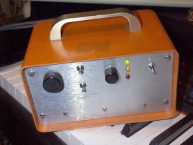
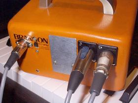
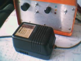
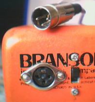
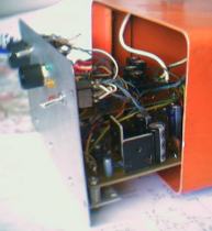
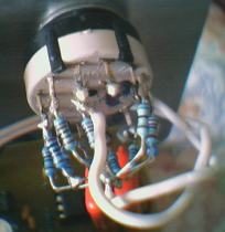
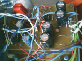
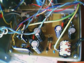
Here's a balanced input microphone preamplifier I'm working on
Intro | Circuit Description | Schematics | Construction | To Do | Photos | Links Introduction
The design is still being revised (suggestions welcome! - see email link below) and has finally been built. I'm fairly happy with the design, but already there are some improvements to be made. This is not designed to be an extremely high quality pre-amp but has pretty good performance. My budget doesn't stretch to top quality mics by any means, nor high-power PC DAW recording setups, but I figure a good mic preamp wouldn't go amiss, and I can learn a thing or two about preamp design along the way. You can download the schematics and PCB layouts from the links below
Circuit Description I've chosen to have a stepped gain control because I already have suitable rotary multi-position switches. A variable resistor can also be used, but a special reverse log taper potentiometer is required to give good control, and these are not so easy to get hold of and probably not worth it unless you're manufacturing loads of preamps. I've used bipolar electrolytic capacitors for coupling the stages. These are a compromise between performance and cost - ideally plastic film caps such as polypropylene should be used, but these are rather expensive and large... I haven't done a head-to-head of plastic film and the bipolar electrolytics, but I don't think the performance hit will be anything to worry about. The same applies to the INA103 gain control decoupling caps. Rane uses a 470uF polarised electrolytic in their MS-1b, but I'm not sure it's such a good idea to use a polarised cap with zero DC bias. I've gone for 1000uF (bipolar electrolytic) or so for slightly better low freq response at higher gains. The -3dB point at 60dB gain in the INA103 is about 55Hz (theoretical - the practical value is probably a bit higher). My PCB layout has space for 5 x 220uF bipolar caps because I can get these cheaper than 1 x 1000uF for a single preamp. Inserting a capacitor in series with the gain set resistor ensures the gain drops off at low frequencies and is unity at DC, which reduces rumble and noise a fair bit, and is probably more stable. The power supply is fairly conventional and provides +/- 15V and +48V regulated. The phantom supply is an interesting design based on the Rane MS-1b (incidentally, Rane's website has a treasure trove of application notes, schematics and audio papers). It triples the input voltage to give about 70V unregulated - only a single 18V transformer is needed. This is regulated down to 48V using a standard LM317 regulator. A series pass transistor and zener diode form a pre-regulator to ensure the LM317's 40V input/output differential limit is not exceeded. Extra smoothing is provided by the R-C filter after the phantom switch. This also slows the rise and fall of the phantom power to soften the switching transients. The power supply will provide power for 2 preamps if clip-on heatsinks are fitted to the regulators. The supply transformer is external to the preamp enclosure in my setup, like a wall-plug unit, but could be built in. I don't have to worry about mains voltages inside the preamp and earth loops/hum aren't a problem (they shouldn't be a problem with balanced connections anyway :-). The mains earth connection can easily be removed if desired. The overload indicator circuit is nothing special. Full-wave peak detection of the signal level at two points triggers an LED briefly if the level goes above a preset level. The first sample point (OL_1) is at the output of the main gain stage to detect the level of the raw audio before any possible filtering - if there is significant low frequency content in the signal and you engage the low cut and rolloff filters, the output level could be much smaller and would not trigger the overload indicator (as sensed at OL_2, the second sampling point, after the filters) despite the input stage being overdriven. The peak level detector also takes account of any possible op-amp offsets, which may be a couple of volts at high gains. I used TL074 and 741 op-amps here simply because I happen to have a bunch of them - almost any quad and single op-amps should do, but check the pinouts. The overload trigger point should be set so the LED illuminates when the signal at OL_1 or OL_2 exceeds about +/- 10V, which is well within the supply rails so no distortion should occur. It's unlikely you'll ever need this signal level at the output...
Schematics and PCB
layout Main
schematic (28K PDF) (GIF
preview) All
schematics and PCB layouts (1688K PDF) (GIF
preview) Eagle
Schematic and PCB files (103K ZIP, Eagle 4.09 format) Make sure you download the tutorial (PDF file) as well if you haven't used Eagle before, since the interface takes a bit of time to get used to, and the online help isn't particularly helpful.
Construction
To-Do Electronically balanced (or servo-balanced as various manufacturers call it) inputs suffer from poor common-mode rejection unless the microphone output and cable are very well balanced (impedance in each source output and each cable conductor must be exactly equal). Small differences in the impedances can drastically reduce the CMRR. Unfortunately, such imbalances are not uncommon in typical studio situations. Jensen Transformers have a bunch of application notes on this and other topics, one of which suggests bootstrapping techniques for improving servo inputs without using a transformer (not that I have anything against transformers, I just want a low-cost preamp). The bootstrapping raises the common-mode impedance from a few kilohms to very high values (megohms) across the audio range and reduces the sensitivity to cable and source imbalances, although it's still not as good as using a transformer. A quick Spice simulation showed that adding the bootstrapping gives a noticeable improvement in CMRR and reduces sensitivity to cable/source imbalances. The output balanced driver could be improved slightly by using a single-chip balanced output driver such as the SSM2142 from Analog Devices. This should give better balancing, and better drive capability. It may be more sensible to use frequencies like 75Hz for the cutoff, and 100/200Hz for the rolloff filters, depending on the mics/instruments you'll be recording. It's easy enough the calculate the required filter capacitor values using the standard filter equations.
Photos
Comments, hints, tips and questions on this design welcome!
Check out CrowleyWeb and the Propeller Clock (with instructions to build your own) Need a cheap DIY microphone to match your preamp? Check out this one. Also check out the SPC electric fiddles! CrowleyWeb | MattWeb | Balanced Mic Preamplifier
© Matthew
Crowley 2003 |