PC-mobile serial interface
by
Luis Padilla Visdómine
Foreword
I have owned several mobiles and since the first one I was curious about
getting it connected to PC but I had not enough information. I was not seriously
interested until I owned a Siemens MC
60 because it does have the capability to connect to computer as it is
stated in the manual. For that purpose Siemens freely provide software (Siemens
Data Suite) and they have cable
accessories (serial and USB) you can buy to link the mobile to PC.
The original cable seemed to me a little bit expensive given the expected
utilization I foresaw (though there are much cheaper clone cables you can buy in
many places). Also I am the kind of person who likes to do by myself as much as
I can, so given both reasons I tried to make my own cable. First, of course, I
had a look in Internet to see if someone had already published a design. I found
a circuit
and some variants based on the MAX232 or MAX3232 integrated circuits. This
scheme looks rather simple and cheap, however I thought I might design something
even simpler and cheaper.
In this article I present a PC-mobile interface using serial port which I
believe the simplest possible while being reliable and safe. It only consists of
two normal transistors, one normal diode (optional, included for better mobile
protection) and three resistors. This circuit was specifically designed for the
Siemens MC60 however it will surely work with most of the Siemens family (I
tested it works with the Siemens M
55 too) as well as very likely with most of other manufacturers: Nokia,
Motorola, Ericsson, Alcatel, etc. Note that this design is highly
experimental and it makes use of some tricks thus having some non standard
behavior. Therefore use it at your own risk and don't blame me if something gets
damaged (though I consider it unlike).
In order to use this design with other mobiles you just need to find out
where the FBUS
TX, RX and GND lines lie within your mobile's interface to know how to wire it
(see some pin outs here and
also here).
I consider the circuit safe enough so that you can then connect it without much
risk and see whether it works. If it does not then it is up to you to find out
the reason. Note that this interface is fine tuned specifically for the Siemens
MC60 so that we can keep it extremely simple. If other mobiles differ
significantly in their electrical behavior of the FBUS (most likely input and
output impedances) then some modifications in the resistors values may be
required in order to make the PC-mobile connection work. If you have some
knowledge of basic electronics you can find yourself the required modifications
because the interface is exhaustively explained step by step in the rest of this
article.
Siemens MC60 interface
Before you even think about connecting your mobile to a PC you first need to
know the mobile IO capabilities. If it has IrDA or Bluetooth then things are
much more easier because no cables are needed, but if the mobile (or the PC) has
not such features you will need a cable which at least must adapt different
connector types. If the mobile has USB lines the cable will be very simple, no
electronics will be needed, just a pin by pin connection with your PC's USB
interface in which getting the mobile connector is the more difficult step.
However the most common IO capability is the serial line, though it is not
in the form of the well known RS-232-C standard of the PC serial port
but in the form of what is called FBUS,
which is similar to TTL (as in PC parallel
port) but with a logic one of about +2.9 volts instead of +5 v. The logic
zero is 0 volts as in TTL. The protocol is the classic serial with start bit,
data bits, parity bit (if any) and stop bit(s). Three pins are involved, one for
transmitting (TX), one for receiving (RX) and ground (GND) which is the common
reference.
Once you decided to go on with the serial cable then look for your mobile's
pinout, at least for the location of the TX, RX and GND lines. Here you can find
some of the most common
mobile pinouts and also here,
be aware however that the pin out may have changed even if the connector is
the same. This happens with the Siemens pin out in the latter link, which is the
one used in older models, in newer models such as the MC60 the pin out is
different and can be found here.
In my case, the MC60 (also valid for the M55), the pin out of the concerned
lines is:
- Pin 2 => GND
- Pin 3 => TX
- Pin 4 => RX
where pin 1 is the leftmost pin when you are
facing the connector with the mobile's keyboard upwards. Note that this pin-out
is different from former Siemens models, it is easy to distinguish both just by
measuring the voltage of the power supply. It uses pins 1 and 2 in both cases
but with reversed polarity, in the older pinout GND is pin 1 while in the newer
pinout GND is pin 2, of course GND is the pin which have negative voltage
compared with the other pin.
The circuit
In principle there is a chance to connect the mobile FBUS directly to the PC
RS232 port and get a working link between both. However a few problems arise if
you try this. On one hand it might be risky to connect a -25/+25 volts signal
(but usually it is about -12/+12) into a device designed for 0/+5 volts input,
but this is not the problem because input and output impedances are usually high
and therefore currents are low enough to be safe. The main problem is that you
may shift the voltage working point of different components and this may lead to
an unpredictable behavior (which ceases when you retire the disturbing voltage).
This problem can be solved with a couple of resistors and one diode.
On the other hand mobiles are very current conservative due to their battery
powered nature, this is noticed in the high output impedance of the TX line.
Output current is so limited that the mobile TX line is unable to drive the RX
input of the PC serial port. This problem can be solved with an external power
supply and one transistor.
Nevertheless there is another problem which complicates things a bit more:
FBUS uses direct logic while RS232C uses inverse logic (not in the control
lines). This means that FBUS represents a logic one setting TX output voltage in
high state (+2.9v) while RS232C codes it with low state (-12v). A logic zero is
showed by FBUS with low state (0v) while it is high state (+12v) in RS232C TX
output. This problem must be solved using some active electronics: an external
power supply and one transistor per line at least.
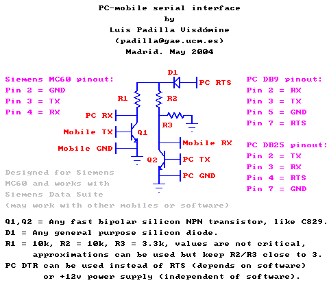
The figure above shows the circuit of the adapter to interface the mobile
with a PC via serial port. You can see it is the simplest solution required to
solve the problems mentioned above. It must be powered with +12v and the best
choice is to take it from one of the two output control lines of the PC serial
port, RTS or DTR. Choose the one that the data exchange software will keep at
+12v all the time (or any if both), in case of the Siemens Data Suite the only
line kept high all the time is RTS. It is almost guaranteed that at lest one of
the two output control lines will be kept up by standard software because the
original data cable must be powered as well.
Resistors R2 and R3 are a voltage divider which adapts the RS232C high state
voltage to the FBUS level, therefore it must be tuned so that the circuit output
for RX of the mobile matches the same voltage as TX of the mobile, usually
around +2.9v. You can do this by using a three leg variable resistor, which will
account for both, R2 and R3. Adjust the variable resistor in two steps, first
without the mobile connected to set a safe level before connecting, then attach
the mobile and fine tune the voltage. Once you are done setting the level you
can measure the resistance of both halves of the variable resistor (from one end
to the cursor and from the cursor to the other end) and now you can replace it
with two equivalent normal resistors which are usually cheaper and smaller (this
might be important to fit the circuit within the box of the PC serial
connector). Actually the output voltage for mobile RX is not so critical and you
can leave it a bit above or below +2.9v, say plus/minus 1v and therefore you can
use the suggested resistor values without any tuning, just check for safety that
the level is acceptable.
The purpose of resistors R1 and R2 is to pull up to high level by default RX
of mobile and PC (note they have different voltages due to R3) when transistors
are closed. When they are open, resistors limit the current and drop voltage
forcing low state of both RX inputs by grounding them (we acknowledge this is
not standard for PC but it works, see next paragraph).
Transistor Q1 is responsible for driving PC RX high when mobile TX is low
and leaving it low when mobile TX is high. Note the inversion of states required
due to the different logic of both ports we commented above. Also note that we
are relaying in a feature of the PC RS232C out of the standard: an open or
grounded input is considered by the UART low state, as if an input of -12v was
driven. This is the only non standard behavior I had to use in this circuit in
order to keep it so simple. All UARTs I have tested behave like that and I had
no problems relaying on that feature.
One might avoid that situation by connecting Q1's emitter to -12v instead of
to ground, but this will introduce the additional requirement of having a -12v
power supply, which we might take from the control line not used to provide
+12v. That is, if we want to avoid an external power supply we will require that
the data exchange software will keep RTS and DTR at +12v and -12v (or
vice-versa) permanently. In case of the Siemens Data Suite it is exactly like
this, maybe Siemens original cable uses this double powering. I traded
simplicity for standard feature and chose a simpler non standard circuit that
works. If you prefer to choose the other option (complexity for standard
behavior) now you know what modification is required to the circuit.
Transistor Q2 is in charge of driving mobile RX up when PC TX goes down and
leaving it low when PC TX is high, note again the inversion of states. Diode D1
has the purpose of protecting the mobile if the power source of the circuit goes
below zero. This happens any time you reboot your computer if you power the
interface with a control line, because the default state of the RS232C output
lines is -12v. If you are so cautious not to connect the mobile to PC before the
software is run or after it has exited then D1 is not strictly needed.
Laptops (troubleshooting)
This interface was designed and tested using a normal clone PC, and though
there is no reason why it shouldn't work with other computers, I found a couple
of problems when used with laptops. The first one is that mobile computers seem
to use less than 12v in their RS232C ports, very likely due to power saving;
I've seen 9v and even 6v. There is nothing wrong with this as long as you take
it into account when you choose the R2/R3 ratio, 9v would require a ratio of 2
and 6v a ratio of 1. If you take this ratio equal to 3 (for the more used RS232C
level of 12v) as suggested in the scheme above, then you might find that the
interface does not work with your laptop even when it does work with other PCs.
If you plan to use the circuit with computers that use very different RS232C
levels, then you have several options. You might have one interface for each
computer, this is feasible because the circuit is cheap and easy to do, however
this does not look like the best solution. Another option is to include a
variable resistor or a switch to select appropriate R2/R3 values given each
computer. Again this solution isn't very clean, I prefer to make just one
interface with a fixed R2/R3 ratio, but set halfway between the values required
by the two computers with more different RS232C levels. This way the input line
of the mobile device will receive less or more voltage than standard when
connected to one or another computer. There shouldn't be problem with this as
there is tolerance with the input voltage. For example, if you want this circuit
to work with 6v and 12v RS232C PC ports, you might choose R2/R3 = 2, then the
mobile RX line will receive 2v and 4v respectively, which is 1v below and above
the standard 3v level. While I think there is no risk feeding the RX line with
4v or even more, I consider 2v somewhat low to work reliably with any mobile, so
actually I would choose a smaller ratio, 1.7 for example.
The second problem I found using the interface with laptops, is that
sometimes more current is needed to drive their RS232C ports. To fix this is
enough to choose a smaller value of R1, for example half the value suggested in
the scheme above, that is, to use 5k instead of 10k.
The cable
There is no special requisites about the cable, signals are strong, low
current and not too high frequency. For my first interface I used a one meter
long thin cable with two twisted pairs, that is, four cables, thought only three
are strictly needed, two cables (one for each twisted pair) are connected to
ground. In my second interface I used an old mouse cable which has the advantage
of already having the PC serial connector (it seems mice use at least TX, RX,
RTS and GND which is what we need), however I cut it away because this kind of
factory made connectors cannot be opened to place the electronics inside.
The circuit can be arranged within the box of the DB-9S or DB-25S PC serial
connector without a PCB, soldering components directly to the pins of the
connector and to neighbor components; some short cables may help but I did not
need to use any. Note that the circuit can be powered there using a control line
of the serial port.
The major problem of this project was the mobile connector. Silly but true.
I started using the connector of a handsfree cable but it was a real headache.
Pins are very small and close one to each other so I had lots of problems
soldering cables with my soldering iron which is not sharp enough. Once I had
cables soldered they broke often because they have to be very thin to be
soldered to one pin and not to touch adjacent pins. Really painful.
One option brought to my attention by a friend who used his imagination (you
should do the same :) when making his personal interface (likely the first
person trying this circuit right after me), is to use the connector of the
charger, which can be opened without damage to insert the three cables needed
for proper connection. Here you have the illustrated
process of making the interface, courtesy of this friend and his digital
camera ;-).
Maybe if you are lucky you'll find a mobile connector well suited for this
project but if you don't or if you like to do everything by yourself (like me)
there is an alternate option: build your own connector. The following
instructions are only valid for Siemens mobiles and those with a similar type of
connector, for other types just use your imagination.
Cut a piece of thick paper or thin cartoon the size of the mobile connector
wide and about four centimeters long. Bend it by half so you get a V shape 2 cm
long which will fit into the mobile connector. Insert the paper with the vertex
toward the mobile and mark with a pen the position of pins 2, 3 and 4 (this is
for Siemens models with the same pin out as the MC60, for some older models you
have to mark other pin positions), pins can not be seen when the paper is
inserted but you can see the beginning of the tracks where they are attached.
Then extract the paper and do a couple of holes per pin with a needle. One
hole must be a couple of millimeters ahead your mark (toward vertex) where you
expect the contact of the corresponding pin of the connector will begin. The
other hole must be done a couple of millimeters before the vertex where you
expect the contact of the corresponding pin of the connector will end.
Now take a very thin copper wire (one of the several hair sized wires that
runs within common low current electric wires), pass it through one hole from
inside the V toward the exterior and then pass it again through the other hole
of the same pin from the exterior toward the inner part of the V. Do this step
for the three pins so that you will get three little copper lines running
parallel which will touch the corresponding pin contacts of the mobile
connector. You've got the idea, uh?
Inside the V you will have three pairs of copper wires, twist each pair so
that you end with only three copper wires, one for each pin. Twist tight to
avoid that cables remain too loose, especially in the side that will make
contact with the mobile connector. To facilitate the soldering of these thin
copper wires with the normal cable wires make another three holes with the
needle half a centimeter before the outer end of the paper connector but as much
separated one to each other as possible. Now pass the copper wires through each
corresponding hole from inside the V toward the exterior. This will help to
solder the external cable preventing that copper wires touch each other inside
or outside the V (though there are other methods like using adhesive tape to
isolate them or using copper cables from a transformer which are already
isolated, but in this case you have to remove the isolation in the part of the
cables that will make contact with the mobile pins).
It only remains to solder the external cables to the connector cables and
fix the connector with adhesive tape so it gets firm, stable and cables do not
move. Before fixing the connector with tape it is convenient to fill the V with
another V identical to the other (but without holes or cables, of course) so
that the connector fits tight into the mobile socket and it is not left too
loose. This will add pressure to prevent accidental extraction of the connector
and to force the connection between the connector and the mobile contacts.
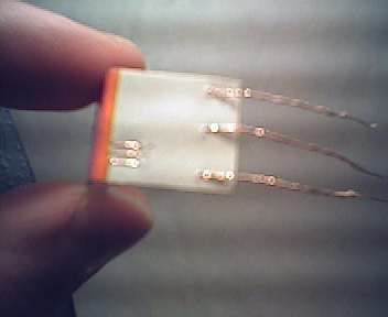
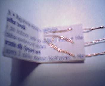
After the problems I had with the original connector I made this one and it
worked at first try. Now is my preferred connector. Here you have a couple of
images (outer and inner views) of the connector so you get an impression. By the
way, pictures were taken with the MC60 integrated camera, you can see it is not
very good for close ups (it isn't good for long distance images as well, best
performance is achieved with photos of people, that is, mid range).
The software
That's a key point, without it the PC-mobile cable is useless. Some
manufacturers provide custom software specific for their mobiles like Siemens
Data Suite, Nokia Data Suite, etc. I don't know how similar are the
protocols, commands, etc. of different manufacturers or even if is there any
standard, maybe they share some basic operations like SMS handling, etc. so that
you can use the same software with different mobiles. It is for example curious
that many anonymous SIM-lock removers and other utilities may be found in a lot
of GSM dedicated sites. Where does people get the knowledge of the protocol and
commands if it is not published anywhere? This seems to be a matter of research
and experimentation, it's up to you!
The software for firmware update provided by Siemens also works (I updated
my MC60 with it) but it seems that unlockers, loggers, etc. do not work with
this interface because it is a data cable and not an unlock
cable which is different but I don't know the difference yet, please tell me if
you know it! It seems that external powering is required in order to boot the
phone with custom software, here is a hint of how an unlock
cable might look. Another possibility seems to be the use of the auto
ignition feature like in this circuit. If any of
these is the case then my circuit might also be used for an unlock cable
provided you add the external power supply and the short circuit with the other
lines or the auto ignition connection, depending on the case.
Another software that works with this interface is the Windows HyperTerminal
because it raises RTS, I tested it on Windows 98 and Windows XP. Using this
program you can type an AT command and you get the OK answer from the MC60
internal modem! The mobile works with any PC COM speed, so set it for 115200
bauds, 8 data bits, no parity and 1 stop bit and you will reach the top speed.
By the way, the Siemens GPRS software does not work with this interface, it does
not detect the mobile. As long as, by now, I'm not interested in GPRS
connectivity, I haven't investigated the reason. It might be due to that it uses
hardware handshake and needs other lines apart from TX and RX (the MC60 seems to
have several such additional serial lines). If this is the case, one can use the
same circuit to interface those lines between the PC and the mobile, just like
with TX/RX lines, however some tests are required to find out the exact lines.
Nevertheless the problem might be much simpler and just be a matter of
shortcircuiting certain lines, like in the handsfree kit. If you find it out,
let me know! ;-)
If you try this design with a mobile different from what I tested please
tell me and I will include it in the list of successfully tested mobiles. Have
fun with your mobile!
padilla@gae.ucm.es
(31-Aug-2004) My PGP public
key.This link:
http://www.gae.ucm.es/~padilla/extrawork/mobile.html

 Go to the
parent page: Cheap Hi-Tech.
Go to the
parent page: Cheap Hi-Tech.