To conclude, here is the output of the program after reading a standard IATA
track (Lufthansa boarding pass):
Bad clocking bits parameter. Using defaults.
Reading track 1.
Swipe time: 0.33 s.
Time unit: 5.7e-06 s.
Initial duration (sigma) of bits in time units:
0LO:  96.0 (11.0), 1LO:  48.0 ( 5.5)
0HI: 116.7 (12.1), 1HI:  58.4 ( 6.1)
Initial thresholds LO:  73.9,  59.0,  64.0
Initial thresholds HI:  92.5,  70.5,  77.8
000000000000000000000000000000000000000000000000000101000101101110110010010011
010000111011011100001100100110011010000101100000010010101111010100001000100101
000000110110110000111100001100100111001010001101000110101000011111100100110101
010111100101011001110000001000000100000010000001000000100000010001101011001000
000010000001000000100000011111100011010000000000000000000000000000000000000000
00000000000000000000000000000000000000000000000000000000000
Mean duration (sigma) of bits in time units:
0LO:  95.2 ( 8.9), 1LO:  47.9 ( 4.3)
0HI: 115.4 (10.4), 1HI:  59.8 ( 5.6)
Final thresholds LO:  77.4,  56.6,  63.4
Final thresholds HI:  94.7,  71.0,  79.3
Start sentinel found.
%VFRAMADLH 4702 MPADILLA/LUIS      8F    ?
End sentinel found.
LRC OK.
Enhancements
The main problem I found with this device is that it introduces an asymmetry
in the bits read, i.e. the output is not a symmetric square ware, bits at low
level are shorter than bits at high level. The reason for this is that the
default state of the reader is high level, when a magnetic flux reversal induces
high level the output is at high level 100% of the duration of the bit. However
when a flux reversal induces low level it takes some time to change from default
high level, say 4 volts, to the point where the port switches from high to low
state, say 2 volts. It happens a similar thing with the tail of the bit, the
port switches from low to high state before the bit has ended. The net effect is
that low bits are shorter (the port is actually at low level only a fraction of
the real bit duration) and high bits are longer because the time stolen to the
low bits is added to the high bits (compare the values of 0LO and 1LO to 0HI and
1HI in the example above to see the difference). If the input signal were a
perfect square wave with sharp vertical edges and the amplifier had a perfect
response then this transition time from high to low state (and vice versa) would
be negligible, but it is not the case.
At first I thought this effect was due to a problem in the design of the
amplifier only, but then I realized there was an additional reason. The classic
text Card-O-Rama:
Magnetic Stripe Technology and Beyond states that the output of the magnetic
head when swiping a magnetic track is a square wave, however this is not true.
The actual output consists of a string of alternating positive and negative
peaks, see this document (alternate
location) for a detailed explanation including plots and see also my new
reader page for some real data pictures (but take into account that these
data are captured with a sound card and thus implicitly filtered with a narrow
passband, hence the difference with the other document's plots). Therefore after
a low level peak there is a time corresponding to the low level bit in which the
reader goes into default state, that is, high level, and thus shortening the
duration of the low level bit (and enlarging the neighbor high level bit).
Of course if you swipe a card quickly enough, specially if it is a high
density track, the string of peaks would resemble a square wave, as you will see
in my
real data pictures (note the difference between the high and low density
profiles). A similar thing would happen if the amplifier had poor response to
high frequencies (like my design). Thus the effect can be compensated and is
less prejudicial than one would first expect. To fix the other problem, the
asymmetry, I took it into account in the software by measuring the duration of
the bits using two different variables, one for low level bits and another one
for high level bits (the LO and HI suffix of the variables as shown above).
Therefore that's the reason why my reader really works, because both problems
can be fixed. Nevertheless the reader (hardware and software) can still be
improved in several ways, but I will not do it because I consider this project
closed as long as I moved to my new and
simpler reader. I will just give a few ideas from the theoretical point of
view and it would be your work to test them, because they may have prejudicial
side effects or require some tuning.
Obviously one the best improvements would be to use a better circuit, you
may try one of the designs in my Magnetic stripe
reader/writer page if you find them better than mine (you might still use my
software). Assuming you choose my amplifier (mainly due to its simplicity, I
presume) there are a few modifications which I believe would fix the asymmetry
problem and give another advantages (more simplicity and protection of the PC
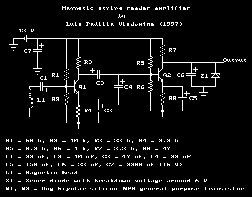
port). The design would be simpler if we remove the Zener diode Z1 in parallel
with the output, which is the only exotic component (well, no really so exotic
:), apart from the magnetic head which is unavoidable, and put a normal diode in
series with the output like this:
                    Amplifier output o-----|<|-----o PC port
                                         Diode D1
This gives a perfect protection of the PC port because the reverse breakdown
voltage of a normal diode is several hundreds volts. Note that now the default
high level state is maintained by the internal pull-up resistor of the port and
no longer by the collector of transistor Q2. The DC current which formerly
flowed from Q2's collector toward the PC port when a high state bit was read is
now stopped by diode D1. This current is no longer needed because the port is
already at high state due to the pull-up resistor. However when a low level bit
is being read D1 let the current flow from the PC port to Q2's collector (and
from there to ground) thus changing the state of the port from high to low
state. This was the first enhancement I tried, but I did not publish it because
it has a bad side effect: it worsens the asymmetry. This is due to the voltage
drop of the diode (around 0.6 V for silicon diodes and about half of that for
germanium type) which enlarges the gap that the low level flux reversal has to
overcome to change the port from high to low state.
Now I have an idea about how to remove the asymmetry but I have not tried
it, however you can test it. It's based on something which I had previously done
in my old DAC-ADC design with
success. In order to minimize the time needed for the low level flux reversal to
switch the port from high to low state we must reduce the gap it has to
overcome. We can do this by simply adjusting (not swiping any card) the
resistance R6 so that the voltage output of the circuit is set at the minimum
level which leave the PC port in high state. The best way to achieve it is to
adjust R6 while running a program monitoring the status of the port (it can be a
modified version of the program to use the reader), you will get to a point in
which a little variation of R6 will change the status of the port. Leave R6 at
this point but where the status of the port is stably high, to avoid false
changes to low level when reading real data. With this adjustment when a
negative flux reversal is read it will almost immediately change the status of
the PC port from high to low state and therefore we record the real duration of
the low level bit.
We can reduce the problem induced because the input signal (output from
magnetic head) is not a square wave but a string of peaks by adding a couple of
low pass RC filters (also known as integrators) so that peaks fall down slowly.
You can do it by adding a couple of resistors (which we will call R9 and R10) in
series with the circuit and raising the values of capacitors C4 and C6. It would
be something like this (I only draw affected parts):
                 C3     R9                                    R10
          ... ---| |---\/\/\---+--- ...               ... ---\/\/\---+--- ...
                              _|_                                   _|_
                           C4 ___                                C6 ___
                               |                                     |
                              ...                                   ...
You have to choose R9 = R10 and C4 = C6 and so that R9(Ohms) * C4(Farads) ~
0.001(seconds) which corresponds to a cut frequency of 1 kHz. This can be
achieved with R9 = R10 = 1 kOhm and C4 = C6 = 1 uF, however I'm not sure about
the optimum values so you can take R9 and R10 as variable resistors and do some
fine tuning. You can test each setting reading real tracks and observing when
you get better results: an increase in the read-out success rate and better
numbers in the output: 0LO closer to 0HI, etc. Of course if you have an
oscilloscope (or a sound card acting like one) is trivial to see whether the
results are better or not.
Independently whether you try this hardware enhancements or not, in
principle you can fix the two problems I mention above (asymmetry and peaks
instead of square waves) by improving the software. Both problems are irrelevant
if we measure the separation between peaks (this is the technique I used with my
new reader) instead of measuring the duration of peaks or pseudo square waves
(the technique used with this old reader). The problem here is that the PC port
does not provide information about the relative level of the input signal, just
whether it is above threshold or below. If we assume that the center of the
peaks are located half way between consecutive changes of port status (this is a
somewhat risky supposition) then we just have to measure the time between the
center of the square waves the port is recording instead of measuring the time
between status changes of the port level. This is rather easy to implement in my
program, only a few modifications are required.
If you manage to remove both problems, either by hardware or by software
improvements, you will be able to simplify the software because the different
treatment of high and low level bits can be skipped, they can be managed as
equivalents. This would make the software more robust because it increases the
statistics of the bits (we approximately double it). In the end all is redundant
in getting a more reliable reader which will require less swipes to read a card
without errors. All these advices given in this final section had not been tried
by me and you should experiment with them only if you like to play with
electronics. If you just want to read cards with a minimal effort you should
forget this device and try my new
reader.
padilla@gae.ucm.es
(10-Feb-2003) My PGP public
key.This link:
http://www.gae.ucm.es/~padilla/extrawork/magamp.html

 Go to
the parent page: Magnetic stripe reader.
Go to
the parent page: Magnetic stripe reader.